140.0 80.0 2× Ø14
Mechanical Design Engineer
Send the sketch.
Get files that build.
We turn rough ideas, napkin sketches and half-finished models into production-ready CAD and manufacturing files — drawings the shop floor can actually cut, bend and assemble without calling you back.
Proof, not adjectives
See the files before you send anything.
A drawing can look correct and still fail under load, choke on flow, or cost a fortune to assemble. We run the numbers first — so the expensive discovery happens on screen, not on the shop floor.
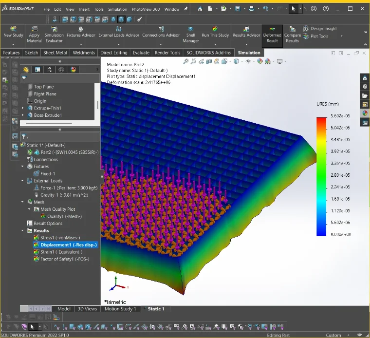 FEA
FEA
Finite Element Analysis
Stress, deflection and safety factor checked under real load cases in SolidWorks Simulation. We find the thin wall or the sharp corner before it cracks in service — and remove material where it is doing nothing but adding cost.
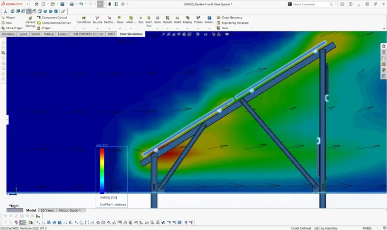 CFD
CFD
Computational Fluid Dynamics
Flow, pressure drop and thermal behaviour modelled in SolidWorks Flow Simulation. Useful when a duct, manifold or enclosure has to move air or fluid predictably, and guessing the geometry is not good enough.
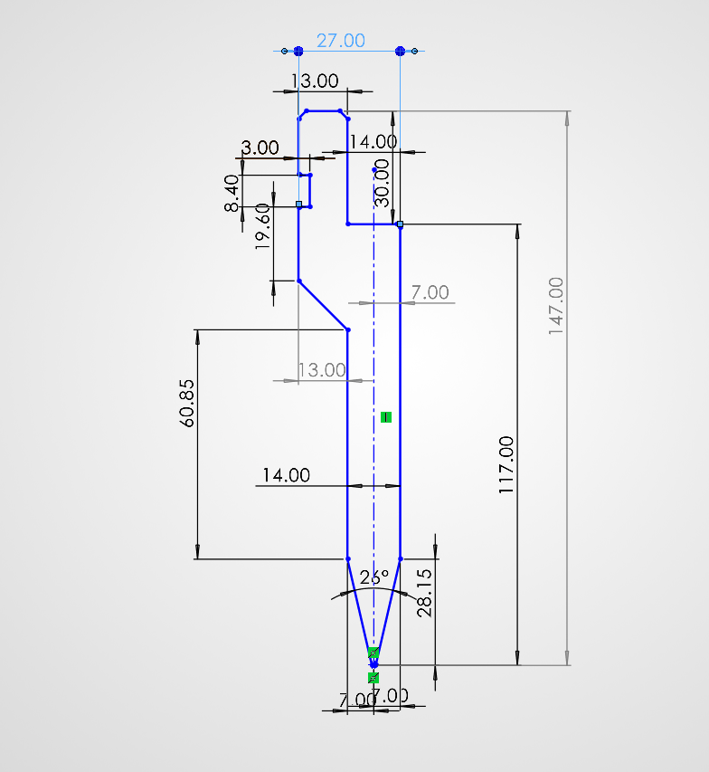 DFMA
DFMA
Design for Manufacture & Assembly
Part count, tooling access, fastener choice and build sequence reviewed before release. Fewer parts, fewer operations, fewer chances for the line to put it together wrong.
Working with Ramzi was a great experience! He delivered high-quality work on time and communicated clearly throughout the project. I highly recommend him and would gladly collaborate again.
Verified Upwork Client — Product Design (CAD), Metal Carports & Solar Mounting Structure
How we work
We do not hand off a drawing until it has proven it can be built.
What we do
Design that survives the shop floor.
Most CAD looks fine on screen and fails in production. We design around the process from the first sketch — so tolerances, bend radii and tooling are right before anything gets quoted. Early on we were losing close to 20% of every sheet to layout and design choices. Designing for manufacture from the first sketch is what fixed it.
01
Sheet Metal Design
Flat patterns, bend allowances and weldments built to your machine’s real capability — not theoretical geometry.
02
Laser Cutting
Cut-ready geometry and nesting for fibre laser — flat patterns, lead-ins and part spacing prepared in CNCKAD, Cypcut and TubesT.
03
Weldments & Metallic Structures
Frames, skids, brackets and structures detailed for the welder — joint access, fit-up, distortion control and weld symbols that mean something on the floor.
04
CNC Machining
Machinable parts with sane tolerances, clear GD&T and drawings a machinist can quote from directly.
05
3D Printing
Print-ready geometry tuned for the process — wall thickness, orientation and supports handled up front.
06
Injection Molding
Draft angles, uniform walls and parting lines designed in early, so tooling quotes come back reasonable.
07
Aluminium Extrusion Dies
Profile and die design for aluminium extrusion, or part design that works inside an existing die. Wall balance, tongue ratio and draw settled before tooling is cut.
08
Sheet Metal Blanking Dies
Blanking and piercing die sets — strip layout, punch and die clearance, material utilisation. Or part design a die can produce without a redesign.
Trusted by
Recent work, by project type.
Germany
Architectural metalwork
Canada
Corten steel design
Algeria
Sheet metal
Romania
Sheet metal processing
United States
Outdoor furniture
Worldwide
Upwork clients
Case studies
A closer look at recent work.
Sheet Metal · Structural
Metal Carport
A fabrication shop needed a carport taken from concept to shop-ready files — full frame and bracket design, with bend angles and weld joints worked out so the shop wasn’t guessing.
Delivered: DXF/DWG cutting and bending files, bend tables, assembly drawings.
Sheet Metal · DFM
Solar Mounting Structure
Designed for a full production run, not a single prototype — DFM rules built in from the start, then the nest validated for material efficiency.
Delivered: Production DXF files, bend table, toleranced drawing set.
Laser Cutting
Privacy Screen
Decorative panel geometry with laser kerf compensation built in, then nested to keep material drop low across the sheet.
Delivered: Cut-ready DXF files, nested layout sized to stock.
Technical Drawings
Stainless Steel Sneeze Guard Post
3D working drawings for a stainless steel mounting post, ready to hand straight to the fabricator with no back-and-forth on spec.
Delivered: Toleranced working drawings (PDF/DWG), material callouts included.
FAQ
Questions clients usually ask.
Project scope and process
What is your product development process?
From a sketch, rough dimensions, or a reference part to production-ready files: I review what you send, confirm the material/process/quantities, then move through concept, detailed 3D modeling, and final manufacturing drawings — checking manufacturability (DFM) at each stage, not just at the end. For anything with real load or thermal requirements, FEA/CFD simulation gets folded in before the design is finalized.
How do you handle design changes or revisions?
Projects are scoped and quoted per milestone before work starts (deposit/milestone-based). Changes within the agreed scope are expected and worked through together. A revision that changes the scope itself — new requirements, a different process, added parts — gets a quick conversation about timeline and price before I proceed, so there are no surprises.
What inputs do you need to start a project?
Whatever you have. A napkin sketch, rough dimensions, an existing model, a sample part, or a full spec — I turn what you send into production-ready CAD and manufacturing files. If something’s missing (material, quantity, target process), I’ll ask before starting.
Deliverables and formats
What file formats will I receive upon completion?
Production-ready CAD (STEP, plus native SolidWorks files on request) and manufacturing drawings as DXF/DWG for cutting and bending, or PDF for detailed technical drawings. STL files come with anything going to 3D printing.
Do you provide prototyping or manufacturing support?
I prepare the files your shop actually needs to run — G-code and cut files for CNC and laser cutting, print-ready STL for 3D printing, DFM-checked models for injection molding — so there’s no back-and-forth translating a “pretty” model into something manufacturable. I don’t run the machines myself; the goal is handing your fabricator or print farm files that work the first time.
Technical and software capabilities
What CAD and simulation software do you use?
SolidWorks for CAD, CNCKAD for sheet-metal nesting, Cypcut and TubeSt for CNC/laser and tube programming, and Geomagic Design X for reverse engineering from scans or samples. FEA and CFD simulation are used to validate structural and thermal performance before a design goes to production.
How do you ensure manufacturability (DFM)?
Every design gets checked against the realities of its target process before drawings go out — bend angles and relief holes for sheet metal, wall thickness and orientation for 3D printing, draft angles and undercuts for injection molding, kerf compensation and nesting for laser cutting. The goal is a file your shop can run without sending it back for rework.
Cost and timeline
How much does a mechanical design service cost?
Most projects are quoted as a fixed price based on scope rather than an hourly rate, typically landing between $200 and a few thousand dollars depending on complexity, part count, and deliverables needed. Send over your sketch or spec and I’ll quote a fixed price before any work starts.
How long will the design phase take?
It depends on complexity — a single bracket moves faster than a multi-part assembly with FEA validation. I’ll give you a realistic timeline once I’ve seen what you need, and I typically reply to new enquiries within four hours so you’re not left waiting on a quote.
Next step
Tell us what you need built.
A napkin sketch, a half-finished model, a photo of the part on the bench — send whatever you have. A design engineer looks at it directly, no sales rep in between, and you hear back the same day.
From past projects